Lines are secondary chart objects. Lines connect symbols, and their existence depends on the existence of the symbols they connect. When symbols are moved or removed from a chart, any lines that connect to those symbols are modified or deleted accordingly. Lines have the following properties:
| Source | The identification of the symbol from which the line begins. |
| Exit Point | The side (top, bottom, left, right) and attachment point of the source symbol to which the line connects. |
| Destination | The identification of the symbol into which the line terminates. |
| Entry Point | The side and attachment point of the destination symbol to which the line connects. |
| Line Style | The pen style (solid, dash, dot) and thickness of the line. Also the type of route (auto, direct, curve) of the line, the size and number of arrowheads, and the text and location of a label for the line. |
| Color | The color of the line and label text. |
Lines that are added to a chart take on the current default properties for lines.
A line may be added between two different symbols. The exit and entry points for the line are determined by how you designate the start and stop points. A line will exit the attachment point and side of the symbol nearest the initial drawing point. Similarly, a line will enter the attachment point and side of the symbol nearest the final drawing point.
Click on the ![]() Tool Bar button,
press Tab, or choose the Line Add command. You may
also use the right mouse button to add a line. Click and
hold the button with the cursor inside the source symbol, and near
the desired exit attachment point and side. Drag a line to
the destination symbol stopping inside the symbol near the the
desired entry attachment point and side. See Figure 5-1.
Release the button to complete the operation. The line will be
routed automatically.
Tool Bar button,
press Tab, or choose the Line Add command. You may
also use the right mouse button to add a line. Click and
hold the button with the cursor inside the source symbol, and near
the desired exit attachment point and side. Drag a line to
the destination symbol stopping inside the symbol near the the
desired entry attachment point and side. See Figure 5-1.
Release the button to complete the operation. The line will be
routed automatically.
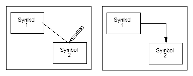
Figure 5-1
Adding A Line
The attachment points for lines on symbols can be made visible by checking the View Line Attach Points command. The number of line attachment points on symbols is chosen with the Options Line Attach Points... command. There may be 1, 3, or 7 attachment points on each symbol side. Refer to Chapter 7: Options.
Line routing takes place automatically after any change to the chart that affects the layout of lines.
The routing process is denoted by the R cursor. Only those lines that need new route calculations are processed. Routing can take significant time when a large chart is first loaded and all line routes have to be calculated.
After any routing failure, the offending line is shown as a thick red direct line, but the line is not deleted automatically. The user can delete the line, add a waypoint, or rearrange the chart so the line will route.
For some purposes, such as Cutting, Copying, Pasting and Deleting, lines are implicitly selected when the symbols they connect to are selected. However, to edit the properties of lines, or to delete them (and not the connected symbols), lines must be explicitly selected. Whenever lines are explicitly selected, all symbols are deselected.
1. Move the cursor to touch the line, where it is not combined with another line but outside the connected symbols. Click the left button, or press Enter
or,
2. Choose the Line Select menu command. Click on the start symbol of the line, drag a line to the end symbol and click again to complete. If more than one line runs between two symbols, one of them will be arbitrarily selected.
When the line is selected, it is drawn in reverse colors, see Figure 5-2.
When selecting additional lines, hold down the Shiftkey to retain previous selections.
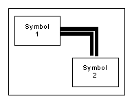
Figure 5-2
Selecting A Line
All of the lines connected to a set of symbols may be selected as follows:
Select the symbols connected to the desired lines. Then choose the Line Pick From Symbol command (Shift+F7). The desired lines will be selected, and the symbols will be deselected.
To delete one or more lines, select them and press Del or choose the Edit Delete command. The selected lines will be deleted.
You can move either end of a line to another symbol attachment point. To move a line end, select the line. Move the cursor to the end of the line that you want to move. When the cursor changes to the Pencil, click on the left mouse button and drag the line end to the new location. Then release the button, and the line will be redrawn to the new location.
If a line fails to route automatically where you want it, you can insert a waypoint in the line and change its route by moving the waypoint. A waypoint is a small rectangluar symbol that is invisible in the drawing, but has a dashed border when seen on the display. This symbol may be moved just like any other symbol, and thereby change the line route. When the operation takes place, the line is split into two segments, connected to the waypoint, which is in the middle of the original route.
To add a waypoint select the line, and choose the Line Add Waypoint (Ctrl+Tab) command. The line will be segmented as described above. You can then drag the waypoint so as to move the line route to the desired location. See Figure 5-3.
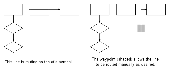
Figure 5-3
Adding A Line Waypoint
With the desired line(s) selected,
click on the ![]() button in the Tool Bar, choose Line Properties... or
press Shift+F4. The Edit Line Style dialog box will be
displayed. See Figure 5-4.
button in the Tool Bar, choose Line Properties... or
press Shift+F4. The Edit Line Style dialog box will be
displayed. See Figure 5-4.
If no lines are selected the Line Properties command selects style for new lines. The sample line in the Tool Bar is drawn with these style settings.
If multiple lines are selected, the Line Properties command displays the common style elements for the selected group of lines.
Style elements that differ in a selected group of lines are not displayed in the dialog box. They may, however, be modified, causing all selected lines to take on the selected styles.
A line Label is an optional short line of text that is displayed near the source or destination of the line, depending on the At dest check box. If one line is selected, type the desired label, if any. in to the Label edit field. When no lines or multiple lines are selected, the Label edit field is disabled. Line labels use the Line Font for the chart. The line font is chosen with the Line Font... command.
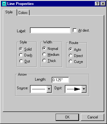
Figure 5-4
Edit Line Properties
When the chart is drawn the label is placed to avoid interference with other chart information. Sometimes the selection and deselection process will interfere with line label drawing. If you cannot see a label that you just added, select the View Refresh command (F5) to redraw the window.
Line labels for direct style lines follow the slope of the line and run parallel to the line, by default. You can turn off this feature by unchecking the Options Diagonal Labels command. When that is done, the line labels for direct style lines are placed in the same manner as those of other line styles.
Auto lines make right angle turns.
Direct lines are straight lines from start point to end point.
Curve lines are arcs drawn such that they exit and enter symbols at right angles to their sides. Curves may be simple or compound ("S" shaped), depending on the placement of the symbols.
Depending upon the route style selection, and end points, a line may not route legally. If a line cannot be routed legally, it will be drawn as a thick direct red line with one arrowhead. The rules is:
For a Direct route, the line may not pass through the source or destination symbol or run along the side of either symbol.
To correct a failed route, move the symbols, change the route style or delete the line.
When using Auto style lines, arrowheads can automatically be placed where lines intersect. This is the default case, which can be disabled by unchecking the Options Auto Fan In command. Figure 5-5 shows and example of this.
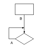
Figure 5-5
Auto Fan-In Example
In this example, the arrowhead for line A has been placed at its junction with line B. Both lines are connected to the top of the diamond. The program has simply moved the arrowhead for line B back to the intersection point for added clarity.
The first line drawn to a symbol attachment point acts as the Main Branch for the fan-in calculation. If you would rather use a different line as the Main Branch, select that line, and choose the Line Main Branch command. This will make the selected line the first line drawn to that attachment point, and all other lines going to the same place will fan in to it.
The line font is used for all line labels. When Chartist starts, it chooses the printer's default font as the chart line font. You may change the line font at any time.
Select the Line Font... command from the menu. The Font dialog box will be displayed. See Figure 5-6. Click on the OK button, or press Enter to complete the operation. All items drawn using the line font will be updated.
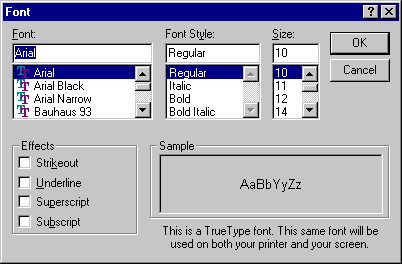
Figure 5-6
Choose Line Font
The current Line Font selection is shown just above the sample line in the Tool Bar.
To select the colors for lines,
click on the ![]() button in the Tool Bar, or choose the Line
Properties... command (Shift+F4).
button in the Tool Bar, or choose the Line
Properties... command (Shift+F4).
When no lines are selected, the colors for new lines are edited. The colors for new lines are shown in the Tool Bar to the right of the color sample for symbols. When multiple lines are selected, the common color elements are shown. Color elements that differ in the selected group of lines are displayed as gray, unless modified in the dialog.
The radio buttons select the color element of the line to be modified. See Figure 5-7 for the Edit Line Colors dialog box.
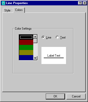
Figure 5-7
Edit Line Colors